

Zahaezuani Rafiq Hamidon*1, Abraham Ryan1, Christine Anderson1, Abdulaziz Alghamdi1, William Caiza1, Robert Wargo1, Yury Faizov2, Sherif Elhanbouly2, Sherif Elazab2, Mohamed El Taher3
1. Turnwell, 2. ADNOC Onshore, 3.SLB
Copyright 2026, Unconventional Resources Technology Conference (URTeC) DOI 10.15530/urtec-2026-4487317
This paper was prepared for presentation at the Unconventional Resources Technology Conference held in Houston, Texas, USA, 22-24 June 2026.
The URTeC Technical Program Committee accepted this presentation on the basis of information contained in an abstract submitted by the author(s). The contents of this paper have not been reviewed by URTeC and URTeC does not warrant the accuracy, reliability, or timeliness of any information herein. All information is the responsibility of and is subject to corrections by the author(s). Any person or entity that relies on any information obtained from this paper does so at their own risk. The information herein does not necessarily reflect any position of URTeC. Any reproduction, distribution, or storage of any part of this paper by anyone other than the author without the written consent of URTeC is prohibited.
Abstract
Post-fracturing plug millout is critical for evaluating unconventional fracturing performance and shaping field development strategies. The UAE’s unconventional field presents harsher downhole conditions than many global unconventional plays, driven by high pressure, high temperature, and elevated H₂S levels. These conditions require a carefully engineered approach as the coiled tubing (CT) and bottomhole assembly (BHA) will be at the limits of their operating envelopes. This paper outlines an optimized, scalable workflow designed to navigate these challenges and reliably execute post-fracturing plug millout operations in the challenging unconventional environment.
High operating wellhead pressures require CT strings with sufficient wall thickness to expand the operating envelope and enable sufficient pump rates to generate turbulent flow for effective solids transport. Furthermore, sour-service constraints limit material selection due to risks of H₂S-induced failure. To reduce CT exposure to the harsh downhole environment, plug selection became a primary planning focus, as rapid plug removal shortens operational time. BHA components were selected to achieve the required pump rate, with lowest pressure drop possible to remain within the operating pressure envelope. The fluid system was engineered to balance low friction pressure with the ability to sustain turbulence for efficient cleanout.
Fit-for-basin dissolvable plugs, selected through engineering assessment and field trials, was proven to maintain integrity during fracturing yet fully dissolved ahead of millout. Pumping strategies were optimized to promote turbulence and maintain slight overbalanced condition to reduce H₂S exposure. These were enabled by simplified BHA consisting of high-rate motor and axial-pulsing extended reach tools, as well as strategic choke management to control the return rate at surface. Quenched and tempered (Q&T) CT strings with hourglass taper design delivered durability, exceeding 500,000 ft of cumulative running footage despite the harsh conditions. Valve-to-valve operating times were achieved below 30 hours for 30-stage wells, validating the overall workflow effectiveness.
Successful execution across more than 30 wells demonstrated the workflow’s repeatability and suitability for the challenging downhole condition. Results confirm that the high-pressure, sour environments can be effectively managed through disciplined engineering and structured planning. The approach establishes a foundation for future development as lateral lengths extend to 10,000 ft and beyond. Proven dissolvable plug performance, combined with an improved understanding of operating parameters, will support further refinement of CT hourglass design, BHA configuration, and surface equipment requirements for the next stage of unconventional field development in the UAE.
Introduction
The UAE has been diversifying energy resources through unconventional development. After significant data collection from the unconventional resource exploration and appraisal phase on 2016-2018, 22 billion bbls recoverable oil and 160 TCF recoverable gas were announced in 2023 attracting many partnerships to develop the resources.
The project started in 2024 by ramping up the unconventional resource operation activities in the Northern and Southern area of Abu Dhabi governorate. A lumpsum turn-key project was assigned to a joint-venture company to drill and complete 144 unconventional wells with different mixtures of oil wells, gas wells, appraisal wells, exploration wells, and development wells. Table 1provides the general well data for both major unconventional areas.
| General Information | North | South |
| Formation Fluid | Gas | Oil |
| Formation Temperature | 320-350 degF | 240-280 degF |
| Formation Pressure | 13,000 psi | 9,000 psi |
| H2S content | 0.5-4% | 100-200 ppm |
Table 1: General Well Information in Major Unconventional Areas in UAE
The project derisks Diyab gas and Shilaif oil resources by having batch drilling and batch completion activities on each area. The well completion project scope includes wellsite management for all rigless completion activities, such as well preparation, fracturing plug and perforation, milling, and flowback operations. Each exploration well on the project is designed to have 15 stages while the development well has 30 stages each, both to be completed using multistage hydraulic fracturing with pump-down plug-and-perforation methodology. Milling operation is then required to provide full wellbore access by removing fracturing plugs.
Before the project had been started, Alhosani et al. (2024) described the execution and technology injection plan for the project. Related to the milling operation, Ryan et al. (2025) describes the initial operational approach for some of unconventional gas wells in the project. During the tenure of the project, there were more technology implementations that improved the general project deliverables. Apart from the general challenges of project acceleration and uncertainties, Hamidon et al. (2026) showcased the initial milling challenges and approach that happened earlier on the project. As the project completed more wells with zipper fracturing methodology, it required more efficient milling operation to optimize the equipment utilization without adding milling resources into the project.
Most of the wells in the project were constructed using 5.5” monobore casing on 8.5” hole. Some wells are completed with 23# casing weight while the majority is using 26#. These wells are cemented using flexible cement and displaced with mud, CaCl2 completion brine, or water in some cases. All wells were undergone multistage hydraulic fracturing with various sand and water ratio. These fracturing stages were isolated using either composite or dissolvable plugs conveyed with wireline in tandem with up to 14 perforation clusters.
Challenges
The UAE unconventional environment presents a uniquely challenging operating envelope compared with many global unconventional developments, primarily due to the combined effects of high pressure, high temperature, and elevated H₂S content.
High Wellhead Pressure and Pump-Rate Constraints
Following hydraulic fracturing, the reservoir and near-wellbore region become supercharged due to the large fluid volume pumped into the formation and the limited time available for pressure dissipation before intervention (Ryan, 2025). This elevated post-fracture reservoir pressure is reflected at surface as increased wellhead pressure (WHP), which consequently limits the ability to pump at high rate for millout as CT circulating pressure can quickly approach equipment or operating limits. Effective plug debris removal depends on achieving sufficient annular velocity and turbulent flow across the horizontal section. If debris generated during milling is not efficiently transported out of the lateral, it can accumulate around the BHA, reduce milling efficiency, increase motor stalls, restrict circulation, and in the worst case, lead to a catastrophic stuck-pipe event.
The pressure challenge becomes more pronounced when comparing oil and gas wells in the UAE unconventional environment. In oil wells, WHP during millout operations is typically in the range of 5,000 to 6,000 psi. In gas wells, even with the wellbore displaced and maintained full of water, WHP can exceed 8,000 psi. Gas wells also introduce additional complexity because the choke cannot be opened aggressively during milling without increasing the risk of gas influx into the wellbore. This requires the operation to balance two competing needs: maintaining sufficient overbalance for well control while pumping at a high enough rate to generate effective debris transport. Historically, under these high-pressure conditions, achievable pump rates were often limited to less than 3 bpm. In a 5.5-in. completion using 2⅜-in. CT, this rate is typically insufficient to reach turbulent flow, compromising cleanup efficiency.
From an equipment integrity perspective, extended operation under high circulating pressure increases fatigue on the CT string and reduces remaining pipe life. The pipe is subjected to repeated bending cycles through the reel, gooseneck, injector, and wellbore trajectory while simultaneously operating under high internal pressure. Continuous pumping near the upper end of the pressure envelope also increases mechanical loading on pumps, fluid ends, valves, seats, seals, and associated high-pressure components. Over long-duration millout operations, this can increase the likelihood of pump-related failures, including damaged packing, washouts, or cracked fluid ends. Any unplanned pump failure can interrupt circulation, reduce debris transport capacity, and increase the risk of solids settling around the BHA. Pressure management must therefore be treated as a system-level challenge involving CT design, BHA pressure drop, fluid friction, pump reliability, choke strategy, and debris transport requirements, rather than as a surface pressure limitation alone.
Elevated H₂S Content and Sour-Service Material Constraints
The UAE unconventional reservoir contains elevated H₂S concentrations, creating a sour-service environment that directly affects CT material selection and operating limits (Ryan, 2025). In oil wells, H₂S concentration is typically expected to range from 200 to 400 ppm. Although this may appear moderate, the combination with high well pressure can result in H₂S partial pressure exceeding the sour-service threshold defined by NACE MR0175/ISO 15156. The challenge is significantly greater in gas wells, where H₂S concentration can range from 2% to 4%, with downhole pressure reaching up to 13,000 psi. Under these conditions, the resulting H₂S partial pressure is substantially higher, creating an aggressive sour environment and limiting the available CT pipe metallurgy that can be safely deployed.
This creates a direct conflict with the pressure requirements described in the previous section. High WHP and circulating pressure demand CT strings with sufficient mechanical capacity, and higher-yield grades may be preferred to expand the operating envelope. However, higher-strength materials are generally more susceptible to sulfide stress cracking (SSC) when exposed to H₂S under tensile stress. NACE MR0175/ISO 15156 imposes strict material requirements for sour service, including hardness limits commonly associated with lower-strength steels, which restricts the application of high-strength CT in sour environments.
As a result, CT selection becomes a constrained engineering trade-off. The pipe must provide adequate pressure capacity and reach capability while maintaining acceptable resistance to SSC. This limitation cannot be managed through metallurgy alone; it requires an integrated approach combining appropriate CT selection, reduced exposure time, corrosion inhibition, H₂S scavenging, pressure management, and real-time pipe integrity monitoring. This further supports the need for a basin-optimized millout workflow that balances high-pressure performance with sour-service risk mitigation.
Engineering Design and Workflow Optimization
The challenges described in the previous section, particularly high wellhead pressure, elevated H₂S content, and pressure-limited pump rates, required an integrated engineering approach rather than isolated equipment changes. Each element of the operation, including frac plug selection, CT string design, BHA configuration, fluid system, and job procedure, was evaluated based on its ability to reduce operational exposure, preserve pressure integrity, and improve cleanout efficiency. The following describes how these design considerations were developed and applied to establish a repeatable workflow for post-frac plug millout in the UAE unconventional environment.
Frac Plug Selection
Two primary types of fracturing plugs are commonly used in unconventional plug-and-perforate completions: composite and dissolvable plugs. Composite plugs are typically constructed from composite materials, although some designs may include cast-iron or steel slips and non-degradable rubber elements. Dissolvable plugs generally use a magnesium-alloy body designed to degrade under specific downhole conditions, with degradable sealing elements and non-dissolvable anchoring buttons.
Each plug type offers advantages and limitations. Composite plugs generally provide more cost-effective isolations, but they require mechanical millout after fracturing. Their removal efficiency depends heavily on plug construction, millability, and debris characteristics. Dissolvable plugs, when properly matched to reservoir temperature, fluid chemistry, salinity, and exposure time, provides reliable zonal isolation while significantly reducing remaining plug material during millout. However, poor field compatibility may result in incomplete dissolution, leaving large, hard fragments in the wellbore. These remnants lead to frequent motor stalls, accelerated BHA wear, premature tool failures, poor debris transport, and increased stuck-pipe risk.
Given the high-pressure, high-temperature (HP/HT), and sour conditions of the UAE unconventional field, plug selection was treated as a critical engineering decision rather than a standard completion choice. Regardless of plug type, the selected design had to maintain reliable zonal isolation under high treating pressure and prolonged exposure, while also supporting efficient post-fracturing removal. For composite plugs, fully composite construction was preferred, with no steel or cast-iron slips, as metallic components had historically been difficult to mill and transport to surface under pressure-limited pumping conditions.
For dissolvable plugs, selection required field-specific qualification. Laboratory dissolution testing was performed using actual fracturing source water to replicate the expected wellbore environment. Since dissolution performance is strongly affected by downhole temperature, fluid salinity, fluid composition, and exposure time, plug material and geometry were evaluated to ensure predictable degradation within the required operational window while maintaining sufficient mechanical integrity during stimulation. The objective was to select a plug that could reliably isolate during fracturing and degrade sufficiently before CT intervention to minimize milling time, debris volume, and sour-environment exposure.
Plug outside diameter (OD) was also an important selection criterion, particularly in wells with potential casing deformation or restricted internal diameter. Slim dissolvable plugs with smaller OD and high expansion capability were considered to improve conveyance through tight spots while maintaining isolation capability. Slim composite plugs were not preferred in these wells because the required undersized mill could core the plug rather than mill it uniformly, leaving large remnants that are difficult to clean out. As a result, plug selection accounted not only for isolation performance, but also accessibility, millability, debris behavior, and compatibility with the CT hydraulic envelope.
CT String Design
The CT string design for the millout campaign was governed by two competing requirements: maintaining pressure integrity under high-WHP conditions while ensuring compatibility with the sour-service environment. As discussed in the preceding pressure and H₂S challenge sections, elevated wellhead pressure reduces the available circulating pressure margin and limits the ability to increase pump rate for effective debris transport. Larger CT sizes are generally preferred because they would reduce friction pressure, allow higher pump rates, and improve annular velocity for solids transport (Alowaid, 2025). On the other side, larger OD CT also has lower collapse resistance, making it less suitable for a high-pressure environment. A 2.375-in. CT string was therefore selected as the most practical balance between pressure rating, hydraulic performance, and operational reach. With appropriate wall thickness and BHA selection, this size provided sufficient hydraulic capacity to support the required pump rates while maintaining the pressure integrity needed for the operating envelope.
Material selection was further constrained by the elevated H₂S content of the reservoir. Conventional sour-service guidance typically limits acceptable CT materials to lower-strength grades due to the increased risk of sulfide stress cracking as yield strength and hardness increase. This created a direct conflict with the need for higher mechanical capacity in high-pressure wells. To address this, quenched-and-tempered (Q&T) CT material was selected because of its improved strength, toughness, fatigue resistance, and demonstrated performance in H₂S-containing environments (Galvan, 2019 and Rolovic, 2017). The initial string design used Q&T 95-ksi material as a conservative sour-service option. As field confidence increased, Q&T 110-ksi material was introduced to expand the operating envelope, allowing thinner wall sections in selected parts of the string while still maintaining adequate pressure and load capacity.
An hourglass taper philosophy was applied to distribute wall thickness according to the localized loading conditions along the well profile. Heavier wall sections were positioned where additional stiffness were required, particularly near the heel and build section. Thinner wall sections were placed across the horizontal lateral to reduce string weight and frictional drag, improving conveyance while minimizing the likelihood of lock-up. The CT designs balance pressure integrity, sour-service material constraints, fatigue management, and hydraulic performance within a single engineered CT string, making it an integral part of the overall basin-optimized millout workflow, rather than a standalone equipment selection.
BHA Selection
BHA selection was driven by the need to achieve effective debris transport while operating within the restricted pressure envelope of the UAE unconventional wells. High-WHP limited the available circulating pressure margin, making it critical for each BHA component to support high pump rates with minimal differential pressure. For a 2.375-in. CT string inside a 5.5-in. completion, the minimum pump rate required to achieve turbulent flow was approximately 4.0 bpm. Therefore, the BHA had to deliver this rate consistently without excessive pressure losses, while remaining robust enough for extended operation in high-pressure, high-temperature, sour-service conditions.
At the beginning of the project, a 2.875-in. motor with a 5/6-lobe, 4.7-stage power section was used. This motor had a maximum pump-rate capability of 4.0 bpm and had proven reliable in regional HP/HT applications (Alowaid, 2025.) As the need for greater hydraulic margin became clearer, a 2.875-in. motor with a 4/5-lobe, 4.0-stage power section was introduced. This design increased maximum flow-rate capability to 5.0 bpm, enabling higher pump rates with lower differential pressure while maintaining speed and torque output.
The same philosophy was applied to the extended reach tool (ERT), where high-rate capability and low pressure-drop were prioritized. An all-metal ERT that generated hydraulic pulsation through engineered inserts was preferred over conventional rotor-stator designs to reduce dependence on elastomers, which are more vulnerable to degradation in high-temperature operations. As the project progressed, larger 3.125-in. motor and ERT configurations were also introduced. These tools delivered similar pump-rate capability with lower differential pressure, making them particularly suitable for wells with WHP exceeding 8,000 psi.
Other BHA components were selected to reduce failure risk and maintain well-control integrity under extreme conditions. A non-pressure-balanced circulation sub was used instead of a conventional burst-disc system to reduce the risk of unintended activation from debris impact or pressure spikes. Critical well-control components, including the CT connector and downhole check valves, were rated to 15,000 psi. Overall, BHA selection focused on maximizing hydraulic efficiency, minimizing pressure losses, reducing elastomer-related failure points, and preserving well-control reliability in high-pressure sour-service operations.
Fluid Selection
Fluid selection played a critical role in achieving effective wellbore cleanout and transporting plug debris to surface. In long horizontal laterals, sufficient annular velocity and turbulent flow are required to keep solids suspended while they are transported along the lateral section. This requirement became more challenging in the UAE unconventional environment because high WHP limited the available circulating pressure margin. Therefore, the fluid system had to support two competing objectives: reduce friction pressure to remain within the operating envelope, while maintaining sufficiently low viscosity to achieve turbulent flow.
Re=928*ρ*v*(d2-d1)60*μ
Figure 1. Reynolds Number Formula for CT Operation (Pope, 2017)
Turbulent flow was evaluated using Reynolds number, with a target value of 20,000 based on the relationship described by Pope (2017) in Figure 1 above. From this relationship, the two controllable parameters that most directly influence turbulence are annular velocity and fluid viscosity. Increasing annular velocity requires higher pump rate, which was already a key focus in the CT string and BHA design. In addition to the string and pipe design, higher pump rate could also be achieved by having suitable friction reducer.
When selecting friction reducer, it is important to consider the viscosity profile that friction reducer could have on the slickwater. For the selected operating configuration of 2.375-in. CT inside a 5.5-in. completion, and with a minimum pump rate requirement of approximately 4.0 bpm, the selected friction reducer had to reduce circulating pressure effectively while maintaining fluid viscosity below approximately 4 cP to support turbulent flow. Friction reducer performance was also found to be sensitive to base-fluid quality and salinity (Lagarrigue, 2025). As a result, the most effective friction reducer was not necessarily universal across all operating areas, and different products demonstrated better performance depending on the specific water source and field conditions. The fluid design therefore requires a practical balance between friction-pressure reduction and viscosity control.
Additional chemical additives were incorporated to address sour-service exposure. In gas wells, where H₂S concentration could exceed 2%, H₂S scavenger was continuously added to the base fluid to reduce sour exposure during circulation. In addition, corrosion inhibitor was pumped to protect the CT string by coating the external pipe surface, both through circulation and through the injection point below the stripper. The final fluid system therefore served multiple functions: reducing friction pressure, preserving turbulent-flow capability, improving solids transport, and supporting the H₂S corrosion inhibition program required for safe and reliable CT operation in the high-pressure sour environment.
Procedural Enhancement
The optimization initiatives described in the previous sections were ultimately integrated into improved field procedures. Increasing pump rate while remaining within the allowable operating envelope was a key enabler, as it provided sufficient hydraulic energy for debris transport and allowed the cleanout sequence to be optimized. Once the CT string design, BHA configuration, and fluid system were aligned to support the required operating parameters, the millout procedure could be executed with greater confidence and efficiency.
Historically, a conservative approach using multiple sweeps was considered a safe practice to ensure adequate wellbore cleanup. However, in the high-pressure sour environment, excessive sweep frequency significantly increased operating time, equipment exposure, fluid consumption, and overall cost. Previous operations had demonstrated that millout could extend up to three days and require multiple CT runs for only 15 plugs, resulting in prolonged exposure of CT pipe, pumps, and surface equipment to high-pressure sour-service conditions. With optimized operating parameters, a more efficient cleanout schedule with fewer sweeps could be executed safely, provided that pump rate, circulating pressure, returns, and debris recovery remained within the defined targets.
A key requirement for this more efficient sequence was systematic monitoring of debris recovery after each plug. For composite plugs, the expected debris weight from each plug type was established using historical field data from the region and relevant global unconventional experience. This provided a practical benchmark to determine whether sufficient debris had been recovered before continuing to the next plug without an additional sweep. For dissolvable plugs, the assessment was less direct because the amount of recoverable debris depended on the extent of dissolution before intervention. In these cases, debris expectation was estimated based on the amount of milling action required. If a plug was drifted without milling, minimal debris was expected. If significant milling was required, corresponding debris recovery at surface was expected before progressing.
To standardize execution and improve consistency across crews, contingency flowcharts were also developed and refined through multiple iterations as additional lessons were captured. These flowcharts provided a structured decision-making process for abnormal events such as poor returns, excessive debris, motor stalls, pressure anomalies, or indications of restricted movement. Beyond supporting real-time execution, the flowcharts became an important knowledge-transfer tool, helping document project learnings and distribute best practices across different CT crews. This procedural enhancement converted individual field lessons into a repeatable workflow that supported safer, faster, and more consistent millout performance.
Results
Table 2 summarizes the distribution of the 36 wells completed during the study period. The wells were generally categorized by lateral length: approximately 3,000-ft laterals for exploration wells and 6,000-ft laterals for appraisal wells. The 3,000-ft laterals typically consisted of 15 stages, while the 6,000-ft laterals typically consisted of 30 stages.
| Well No | Well Type (O/G) | Lateral Category | No of Stage | Plug Type |
| 1 | Gas | 6,000 | 30 | Dissolvable |
| 2 | Gas | 6,000 | 30 | Dissolvable |
| 3 | Gas | 6,000 | 30 | Dissolvable |
| 4 | Gas | 6,000 | 30 | Dissolvable |
| 5 | Gas | 6,000 | 30 | Dissolvable |
| 6 | Gas | 6,000 | 30 | Dissolvable |
| 7 | Gas | 6,000 | 30 | Dissolvable |
| 8 | Gas | 6,000 | 30 | Dissolvable |
| 9 | Gas | 6,000 | 30 | Dissolvable |
| 10 | Gas | 3,000 | 30 | Dissolvable |
| 11 | Gas | 3,000 | 15 | Dissolvable |
| 12 | Oil | 6,000 | 30 | Composite |
| 13 | Oil | 6,000 | 30 | Composite |
| 14 | Oil | 6,000 | 30 | Composite |
| 15 | Oil | 6,000 | 30 | Composite |
| 16 | Oil | 6,000 | 30 | Mixed |
| 17 | Oil | 6,000 | 30 | Composite |
| 18 | Oil | 6,000 | 30 | Mixed |
| 19 | Oil | 6,000 | 30 | Mixed |
| 20 | Oil | 6,000 | 30 | Mixed |
| 21 | Oil | 3,000 | 15 | Dissolvable |
| 22 | Oil | 3,000 | 15 | Composite |
| 23 | Oil | 6,000 | 30 | Composite |
| 24 | Oil | 6,000 | 30 | Composite |
| 25 | Oil | 6,000 | 30 | Composite |
| 26 | Oil | 6,000 | 30 | Composite |
| 27 | Oil | 6,000 | 30 | Composite |
| 28 | Oil | 6,000 | 30 | Composite |
| 29 | Oil | 6,000 | 30 | Composite |
| 30 | Oil | 6,000 | 30 | Composite |
| 31 | Oil | 6,000 | 30 | Composite |
| 32 | Oil | 6,000 | 30 | Composite |
| 33 | Oil | 3,000 | 15 | Composite |
| 34 | Oil | 6,000 | 30 | Composite |
| 35 | Oil | 6,000 | 30 | Composite |
| 36 | Gas | 3,000 | 15 | Composite |
Table 2: List of Completed Wells
Operational Efficiency
Operational efficiency was evaluated based on the number of CT runs required to complete millout and the total valve-to-valve operating time. Across the 36 wells included in the study, 28 wells were completed in a single CT run (Figure 2), demonstrating the repeatability of the optimized workflow under the field’s challenging operating conditions.
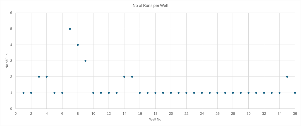
Figure 2: Number of Runs in Each Wells
Only three wells required three or more CT runs to complete the operation. These wells were located on the same pad and were affected by casing deformation. They were also completed during the early phase of the project, when field data was still insufficient to confidently diagnose deformation-related restrictions before intervention. As a result, multiple attempts were required to pass the restrictions and complete the millout. In addition, these wells were part of the early slim dissolvable plug trials, where the selected plug design was later found to be incompatible with the field environment, resulting in incomplete dissolution and more difficult milling conditions.
On average, wells with 30 plugs were milled out in less than 40 hours. In the best-performing cases, where no casing deformation was present and suitable dissolvable plugs were deployed, operations were completed in less than 30 hours valve-to-valve. Valve-to-valve time is defined as the period from initial well opening to final well shut-in after completion of the millout operation.
Reducing the number of CT runs and minimizing operating hours provided benefits beyond operational cost reduction. In a high-pressure, sour environment, limiting intervention duration is critical to reducing CT exposure to H₂S, preserving downhole and surface equipment integrity, lowering fluid consumption, and reducing overall operational risk. Therefore, the core operating principle was to minimize exposure time to the extreme well environment while maintaining safe and effective millout performance.
Plug Behaviour and Performance
Six different fracturing plugs were tested and utilized across the 36 wells as per Table 3 below.
| Plugs | Type | OD |
| Plug A | Dissolvable | Regular |
| Plug B | Dissolvable | Slim |
| Plug C | Dissolvable | Slim |
| Plug D | Composite | Regular |
| Plug E | Composite | Regular |
| Plug F | Composite | Regular |
Table 3: Fracturing Plugs Type & OD
Plug performance data were collected from all 36 wells. Multiple performance indicators were evaluated across the operation, including wireline conveyance, plug setting response, isolation performance during fracturing, and plug behavior during post-frac millout. Table 3 summarizes the plug types evaluated during the study, which included both dissolvable and composite designs, as well as regular and slim outside-diameter configurations.
For millout performance, the key evaluation metric differed by plug type. For composite plugs, the primary metric was the average time required to mill each plug. For dissolvable plugs, the primary metric was drift rate, defined as the percentage of plugs that were passed or drifted without requiring active milling. Drift rate was used as an indicator of dissolution effectiveness prior to CT intervention. Additional performance indicators, including motor stall frequency, debris size, debris behavior, and cost, were also considered to assess the overall suitability of each plug design.
Figure 3 and Figure 4 below summarize the performance of the dissolvable and composite plugs, respectively, based on the plug types listed in Table 3 above. Some wells included more than one plug type. If the secondary plug type represented a significant portion of the well, defined as more than five plugs, both plugs were evaluated independently. If fewer than five plugs of a secondary type were used, only the primary plug type was considered for the performance evaluation.
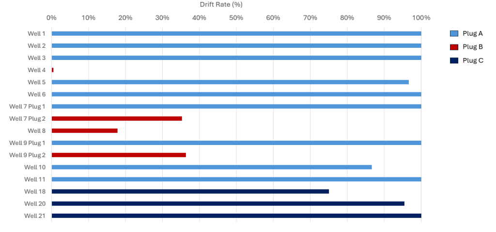
Figure 3: Drift Rate of Different Dissolvable Plugs
Figure 3 shows the drift-rate performance of the dissolvable plugs evaluated during the study, with the following observations:
- Plug A was the primary dissolvable plug selected for the project (Ryan, 2025) and underwent a detailed design and qualification process to confirm compatibility with the field environment and fracturing fluid system. It achieved 100% drift rate in multiple wells, indicating that all plugs were drifted without requiring active milling.
- Despite the strong performance of Plug A, casing deformation cases required the use of slim dissolvable plug options. Plug B was deployed due to availability, although with recognized compatibility risk. Field performance confirmed this limitation, with Plug B achieving less than 40% drift rate in each of the four wells where it was used. The undissolved plug material was difficult to mill and frequently stalled the motor, contributing to premature BHA failures and extended operating time.
- Plug C was later identified as an alternative slim dissolvable option following additional technical due diligence. The plug is significantly smaller in both OD and length, allowing it to pass through the deformed casing, and its material composition was better suited to the downhole environment. Plug C delivered successful performance across the three wells shown in Figure 3, achieving drift rates of more than 75%, 95%, and 100%, respectively. Since Plug C was primarily used as a contingency option for casing deformation cases, it was also deployed successfully in smaller quantities in other wells; however, those wells were not included in Figure 3 or Figure 4because the number of Plug C units used was below the evaluation threshold.
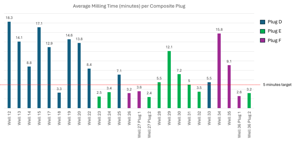
Figure 4: Milling Time per Composite Plugs
Figure 4 shows the average milling time per composite plug, with the following observations:
- Plug D was used as the initial composite plug option for the project. However, its milling performance did not consistently meet the project target of 5 minutes per plug. As a result, Plug E and Plug F were introduced as alternative composite designs to improve millout efficiency.
- Plug E and Plug F both demonstrated improved overall performance. Although the milling time in some wells still exceeded the 5-minute target, both plugs were considered successful due to their more favorable milling behavior. In particular, they generated smaller and lighter debris after milling, which improved solids transport and overall cleanout efficiency.
- Some wells showed longer milling times due to controlled operational trials. For example, in Well 34 and Well 35, Plug F was used while different milling practices were tested to further improve cutting size and debris characteristics. These trials resulted in longer milling time but provided useful insight into optimizing debris generation and cleanup performance.
CT Pipe Management
A total of six CT strings were utilized during the project, covering post-frac plug millout as well as other intervention scopes such as wellbore cleanout and fishing operations. Of these six strings, four have been retired and two remain operationally active. Table 4 summarizes the key design details and cumulative running footage for each string. In general, the strings were based on two primary design philosophies: a conservative Q&T 95-ksi design and a higher-strength Q&T 110-ksi design.
| String No | CT Size | Tapered Design | CT Grade | Total Running FT |
| 1 | 2.375 | 0.224 – 0.250 – 0.224 – 0.250 | Q&T 95 | 273,234 |
| 2 | 2.375 | 0.224 – 0.250 – 0.224 – 0.250 | Q&T 95 | 314,337 |
| 3 | 2.375 | 0.175 – 0.276 – 0.25 – 0.236 – 0.224 | Q&T 110 | 492,831 |
| 4 | 2.375 | 0.175 – 0.276 – 0.25 – 0.236 – 0.224 | Q&T 110 | 502,067 |
| 5 | 2.375 | 0.224 – 0.250 – 0.224 – 0.250 | Q&T 95 | 251,230 |
| 6 | 2.375 | 0.224 – 0.250 – 0.224 – 0.250 | Q&T 95 | 73,203 |
Table 4: CT String Details
String #1 and String #2 were initially designed conservatively using quenched-and-tempered (Q&T) material with 95,000-psi yield strength. This design was selected to address the elevated H₂S content of the wells while maintaining adequate pressure capacity for the high-WHP operating environment. As field experience increased and greater operational confidence was established, a second design was introduced for String #3 and String #4 using higher-strength Q&T material with 110,000-psi yield strength. The higher material grade enabled the minimum wall thickness to be reduced to 0.175 in., creating a lighter pipe section in the horizontal interval and improving reach capability in extended lateral wells.
Despite the higher yield strength, String #3 and String #4 demonstrated strong field performance in the sour-service environment. Post-job inspections showed no evidence of H₂S-induced damage, corrosion pitting, or integrity degradation attributable to sour exposure. The performance of the first four strings demonstrated that both Q&T 95-ksi and Q&T 110-ksi designs were capable of withstanding the extreme downhole conditions while achieving the required operational objectives. String #5 and String #6 were subsequently deployed using the same general design as String #1 and String #2, following consideration of cost, availability, and logistical constraints.
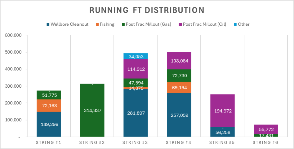
Figure 5: Distribution of jobs for all CT strings. String #5 & #6 still in active service.
Figure 5shows the distribution of jobs across the six CT strings, with the following observations:
- String #1 to String #4 have been retired with no recorded pipe failure. String #4 achieved the highest cumulative running footage, exceeding 500,000 ft before retirement. String #5 and String #6 remain in active service.
- String #2 accumulated approximately 300,000 ft of running footage despite being used exclusively for post-frac millout in gas wells, which represented the most severe operating condition in the campaign. These operations were performed with WHP consistently above 7,000 psi, circulating pressure up to 11,000 psi, and H₂S concentration greater than 2%.
- String #3 and String #4, both Q&T 110-ksi strings, were also deployed in high-H₂S gas wells and demonstrated strong field performance. Post-job pipe integrity inspections showed no H₂S-induced damage, supporting the suitability of the Q&T pipe design and validating the effectiveness of the preventive control measures implemented during the campaign, including the corrosion inhibition program.
Conclusion
The UAE unconventional post-frac millout campaign demonstrated that reliable and efficient CT operations can be achieved in a high-pressure, high-temperature, sour-service environment when the workflow is engineered as an integrated system rather than as a series of independent operational choices. The combination of elevated WHP, pressure-limited pump rates, high H₂S content, and long horizontal laterals created a narrow operating envelope that directly affected CT material selection, BHA configuration, fluid design, debris transport, and procedural adherence.
A basin-optimized workflow was developed to address these constraints. Fracturing plug selection was treated as a critical engineering decision, with dissolvable and composite plug designs evaluated based on isolation performance, field compatibility, drift rate, milling behavior, and debris characteristics. CT string design was optimized using Q&T metallurgy and hourglass taper philosophy to balance sour-service compatibility, pressure capacity, fatigue life, and reach. BHA selection focused on high-rate, low-pressure-drop components that could support turbulent flow while reducing elastomer-related failure risks. Fluid selection balanced friction-pressure reduction with viscosity control to preserve the ability to achieve turbulent flow, while also incorporating H₂S scavenging and corrosion inhibition for sour-service protection. These design elements were then incorporated into improved field procedures, including optimized sweep strategy, debris recovery monitoring, and standardized contingency flowcharts.
Field execution across 36 wells confirmed the effectiveness and repeatability of the workflow. Most wells were completed in a single CT run, with 28 out of 36 wells achieving single-run execution. For 30-plug wells, average millout time was maintained below 40 hours, while the best-performing wells were completed in less than 30 hours valve-to-valve. CT pipe performance further validated the design philosophy, with Q&T 95-ksi and 110-ksi strings demonstrating reliability under high-pressure sour conditions and no recorded H₂S-induced damage based on post-job inspections. Plug performance results also confirmed the importance of field-specific qualification, as properly selected dissolvable plugs achieved high drift rates, while incompatible designs resulted in poor dissolution, motor stalls, extended operating time, and increased debris-related risk.
Overall, the campaign showed that successful post-frac plug millout in the UAE unconventional environment depends on disciplined integration of equipment design, material selection, plug qualification, hydraulic optimization, chemical mitigation, and procedural control. The results support the abstract’s core premise that high-pressure sour environments can be effectively managed through structured engineering and basin-specific workflow development. As future wells progress toward longer laterals of 10,000 ft and beyond, this workflow provides a scalable foundation for further optimization of CT string design, BHA configuration, fluid system selection, surface equipment requirements, and operational practices.
References
- Alhosani, N., Al Shehhi, H., Refaei. A., et al 2024. Mega Hydraulic Fracturing Operations with Innovative Efficiency Transformation. Presented at the Abu Dhabi International Petroleum Exhibition and Conference, Abu Dhabi, 4-7 November., SPE-222591-MS. https://doi.org/10.2118/222591-MS
- Alshammari, H., Baki, S., Hamidon, Z.R., et. al. 2023. Improving Milling Efficiency in HP/HT Unconventional Field by Comprehensive Engineering Design and Strategic Planning of Fracturing Plugs. Presented at the SPE/ICoTA Well Intervention Conference and Exhibition, The Woodlands, 21-22 March 2025. SPE-212938-MS. https://doi.org/10.2118/212938-MS
- Alowaid, A.M., Mechkak, K., Khan, H.A., et. al. 2025. Post-Stimulation Plug Removal in Unconventional Wells with Extended Reach Horizontal Lateral, Leveraging Dissolvable Plugs and Hourglass Coiled Tubing String Design. Presented at the SPE/ICoTA Well Intervention Conference and Exhibition, The Woodlands, 25-26 March 2025. SPE-224093-MS. https://doi.org/10.2118/224093-MS
- Galvan, I., McClelland, G., Gagen, E., et. al. 2019. “In-Line Quench and Temper Technology Applied to CT Improves Safety and Reliability in Extended Reach U.S. Shale Operations.” Paper presented at the SPE/ICoTA Well Intervention Conference and Exhibition, The Woodlands, Texas, USA, March 2019. doi: https://doi.org/10.2118/194255-MS
- Hamidon, Z.R., Ryan, A., Brown, C.A., et. al. 2026. Field-Proven Workflow to Navigate Extreme HP/HT and Sour Environment in UAE Unconventional Gas Field. Presented at the SPE/ICoTA Well Intervention Conference and Exhibition, The Woodlands, 24-25 March 2026. SPE-231358-MS. https://dx.doi.org/10.2118/231358-MS
- Lagarrigue, E., Rachid, R., G., Arali, V., et.al. 2025. Enabling Sustainable Stimulation in Water-Constrained UAE Fields: Next-Generation Ultra-High-Salinity Fracturing Fluids with Integrated Friction Reduction and Scale Control. Presented at the ADIPEC, Abu Dhabi, UAE, 3-6 Nov 2025. SPE-229698-MS. https://doi.org/10.2118/229698-MS
- NACE MR0175/ISO 15156 (Multiple Parts). Petroleum and natural gas industries — Materials for use in H₂S-containing environments in oil and gas production. NACE International / ISO.
- Pope, C., Charlton, A., Inscore, J., et. al. 2017. Stop, Drop and Circulate: An Engineered Approach to Coiled Tubing Drillouts. Presented at SPE Annual Technical Conference and Exhibition, San Antonio, Texas USA, 17 Oct 2025. SPE-187337-MS. https://doi.org/10.2118/187337-MS
- Rolovic, R., Reichert, B., Morales, C., et. al. 2017. Field Performance of New Coiled Tubing Technology and a New Grade for Improved Sour Service. Paper presented at the SPE/ICoTA Coiled Tubing and Well Intervention Conference and Exhibition, Houston, Texas, USA, March 2017. SPE-184796-MS. https://doi.org/10.2118/184796-MS
- Ryan, A., Hamidon, Z.R., Alghamdi, A., et. al. 2025. UAE Unconventional Gas Wells Completion Operation – First Year Learning Curve During Activity Ramp Up. Presented at the ADIPEC, Abu Dhabi, UAE, 3-6 Nov 2025. SPE-229696-MS. https://doi.org/10.2118/229696-MS